László Moholy-Nagy’s Light Prop for an Electric Stage, 1930, is one of the key works in the history of twentieth-century sculpture, standing at the intersection of the histories of kinetic art, of the machine aesthetic, and of material innovation. Building on the artist’s exploration of effects of transparency and movement in his painted and photographic oeuvre, the Light Prop has also had a rich and influential afterlife, too. Under the artist’s supervision, it has been presented as a stage lighting device for abstract theatre (hence its earliest and best title), as a free-standing (immobile) sculpture, and as the main ‘actor’ in an experimental film by the artist. The sculpture has been in the collection of the Busch-Reisinger Museum since 1956. Both before and after 1956, the work suffered damage, alteration, inappropriate restoration, and mechanical instability. The work today stands at some distance from its pristine state: materials are misleading and the movement is so much compromised that it can only be operated for a few minutes every week.

Fig.1
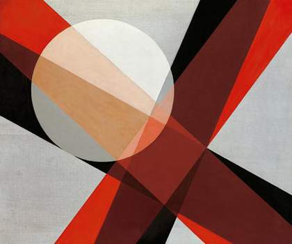
László Moholy-Nagy
Light Prop for an Electric Stage
© Hattula Moholy-Nagy / DACS 2007
A full-sized exhibition replica of Light Prop was commissioned by Tate for the 2006 exhibition of works by Moholy-Nagy and Joseph Albers. The replica was made with the explicit approval of Hattula Moholy-Nagy, the artist’s daughter (and copyright holder), and the concurrence of the two European institutions, Bauhaus Archiv Berlin and Van Abbemuseum, Eindhoven, which own earlier replicas made in 1970. The museum has a signed agreement with Tate and the artist’s daughter setting out the terms of the Harvard University Art Museums’ acquisition of the replica, including such factors as the agreement that the replica be lent, when possible, to major exhibitions; that it not be considered a work of art; that Tate has the right to display the replica for one year in every four.
Through handling and exhibition, Light Prop changed in many ways over time. After shipment to London in 1935, an external frame was added to prevent wobbling. In 1938, after the move to Chicago, the German motor was replaced with an American one. It is likely that the artist replaced the glass spiral and wedge with a metal spiral and an acrylic wedge before his death in 1946. In 1950, the machine came to the Busch-Reisinger Museum on long-term loan. At this point it was in very poor condition, with badly corroded surfaces and a number of missing parts. Missing components were replaced and in 1956 the artist’s wife, Sibyl Moholy-Nagy, gave the object to the museum. Aluminium paint was applied to temporarily hide some of the corroding surfaces and conservator Jack Washeba succeeded in getting it to run ‘for only a few minutes’. Still painted and unmoving, Light Prop was loaned in 1961 to several kinetic sculpture exhibitions in Europe. In 1966 Sibyl Moholy-Nagy, upset by the object’s poor condition, asked to have it back. But, instead, restoration was discussed. The restoration by William Wainwright removed the paint, made the machine run, and, for better or worse, re-plated many components. Serious problems occurred during its subsequent operation at an exhibition in Eindhoven in 1966 and at MOMA in 1968.
The continuing difficulties in running the machine safely led to the decision in 1970 to have an engineering instructor, Woodie Flowers of MIT create two working replicas, now in Eindhoven and Berlin. Copyright permission for these replicas was obtained from Sibyl Moholy-Nagy. Flowers’s work was assisted by the research of a Harvard graduate student, Nan Piene. Concerning the copies, Piene wrote: ‘Given Moholy’s prophecies about multiples and his ordering of enamel “paintings” over the telephone from a sign factory in 1922, as well as his devotion to the light machine and his regret that it was hardly appreciated in his lifetime, one can imagine that the artist would applaud the fact of the replicas.’
The new 2006 replica makes it possible for the art museums to run the device on a regular basis, providing the public a better understanding of the original, which is displayed nearby. The replica has been displayed with its own slightly darkened room where a repeated showing of the six-minute 1930 film of the original by Moholy-Nagy, Light Play: Black, White, Gray, was projected on a wall. Low, directional light illuminated the moving machinery, throwing reflections around the room and projecting moving shadows on one wall.
The replica was made by German engineer and fabricator, Juergen Steger. After careful study of Moholy-Nagy’s 1930 photographs, the 1930 film, and the original sculpture, Steger created a CAD file of the object. This made it easier to visualise components and their movement as he worked on the project in Germany, and to submit drawings for the fabrication of many components. The art museums received a copy of the CAD file along with the replica. Better support at the base made it possible for the Steger copy to eliminate the arching frame added to stabilise the original, and a glass spiral and wedge were fabricated to match the artist’s 1930 design. The variety of surface finishes were also intended to match the original appearance rather than current, damaged and chromed finishes of the artwork. Several slight adjustments were made to help ensure better, more reliable operation. Notes on these variations and on general issues related to running and maintaining the replica were made by staff members when Mr Steger was in Cambridge. As they provide insight into some of the subtleties of design, operation and maintenance, they are appended to this document.
Light Prop replica
Notes from discussions with the fabricator Juergen Steger (JS) during his visit to HUAM to tune up the machine and repaint damaged paint surfaces, 5/8/07.
Henry Lie and Angela Chang
General design
- JS made design decisions by balancing an interested in replicating the original and a need for the replica to function regularly and travel.
- JS used metric units for ‘a more precise replica’. Woody Flowers used US units.
- Chain in US units: 106 links, ½ inch.
- The central rod of original is not one piece. Below main platform, JS took Flowers’s suggestion to use separate rod under the main platform.
- The top bearing is larger and better than on the original. Larger was a compromise to achieve less friction.
Materials
- Rectangular frame elements are welded aluminium for strength. The original was unstable and poorly fixed to the central pole.
- A Plexi panel was substituted for cellulose acetate. JS found a source for acetate sheets in Switzerland, but it was too flimsy and did not appear different from the Plexi. He tried unsuccessfully to layer the acetate to make it stiffer.
- JS’s platform was made in layers: two layers of aluminium core screwed together, 1 mm metal top and bottom, 2 cm ring of wood around the periphery. The original was wood and had slumped from the weight of the elements resting on it. JS was very proud of his platform design.
Cam hole
- JS copied the shape of Flowers’s adjusted cam hole for the flags in the lower platform. It is broader than the original and allows for a smooth rotation of the flags. The original hole had more acute angles which prevented the flags from following the contour of the hole and caused the flags to bind and stop the machine. Flowers corrected this shape and this facsimile copies that adjustment.
- JS did not believe that the movies of the original truly captured the action of the Light Prop because it ran too smoothly. Perhaps someone was manipulating it for filming?
- The frame on the original was likely added to stabilise the centre. Stability issues probably derived from strain caused by the cam hole angle.
Flags
- Springs above flags: JS calculated the tension and strength needed for the springs above the flags to function optimally. Flowers’s replica had a spring encircling the tips of the poles to control their tension.
- JS added bronze fittings at the top of the flags to attach the springs to the poles. They differ from the original, but allow better (less) friction in the rotational movement of the flags.
- The nylon washers fitted to the flags where they move in their slots lessen friction. A nylon insert is also present in a tiny groove at the cam hole in the lower platform. A small amount of grease was also applied to these nylon surfaces – this is important to keep friction down.
Double helix pole and box
- The small bronze tab that slides in the spiral slot of the large rotating column wears over time and will need replacement. JS prepared one spare for us (see his photos). The sharp end needs filing to slide properly, with the leading edge slightly smaller than the rest. To fit it into the securing block’s chamber, it must be pushed deeper into the mount hole than in its operating position (which must fully engage the cylinder groove). Also, to assist fitting in the block’s chamber, it will be necessary to file a little off the top of the blade and a little of the back of the blade (the latter so the tab will recess farther into the block’s hole and allow more clearance during insertion). A securing screw in the block holds the tab in the more engaged operating position. When a new tab (or several) is needed, it will help to give the machinist the drawing from the CAD drawing for this part.
- During his visit, JS cleaned and re-greased the pole.
- Flowers covered the grooved pole for ‘safety’ reasons. JS thinks he may have had technical difficulty with it.
- JS replaced brass (est.) tab that moves within the grooved pole. After one year of running, the previous one was considerably worn with deep grooves. This tab can be checked for wear by moving the box manually (up & down).
- Tab has to be long enough to span the crosses (X) along the pole. Rounded edges are needed to glide past the corners in the X. Filing may need to be done to adjust the edges.
- JS gave us a supply of replacements.
- The tab design was based on Flowers’s replica. JS did not know how the original was made.
- JS: the only surviving drawing of the original box does not accurately represent its manufacture.
- Clutch will prevent the box from dropping.
- HDPE 2 rings inside box to slide up and down double helix. Spindel Gleitlager (?).
- Loctite adhesive was used on some screws to prevent loosening. They will yield with a little more torque when disassembly is needed. There are no ‘left-handed’ screws.
Glass rod
- The glass spiral was based on design (drawings?), not on photos or the art film. It was successfully made on the glass fabricator’s fifth attempt in two parts, the spiral and the rod. The spiral was formed on a metal rod, removed, and attached to the glass rod at the top and bottom. Forming them together resulted in slumping of the assembly.
- JS thought the original glass spiral rod may have been a found object.
- Moholy-Nagy substituted a metal spiral rod after the glass one broke.
- We should consider having a spare glass spiral and wedge made in case of breakage.
Ball
- The ball is not painted black (like the original) for any particular reason.
Surfaces
- JS could not determine original surface colours. Archival pictures showed only differences in texture (e.g. polished vs. matte).
- All the surfaces that appear frosted are spray-painted. Nothing was be textured by sand-blasting. Some paint was damaged during the shipment from Europe and NYC. This visit included repainting the lower disk plane. The large perforated vertical disk was repainted prior to this visit.
- JS chose a single matte appearance with his choice of the grey paint: Glasurit brand Seidenmatt Metallhaftfarbe Kunstharzbasis. Colour: Metallic. Mfg: Akzo Nobel. www.color.de
- The large pierced and painted disk should be secured during transit.
- JS cleaned the chrome with Shellsol to remove ‘halos’ of tarnish. Mineral spirits can be used for chrome and painted surfaces.
- Touch-ups can be done with a brush.
- JS thinned grey paint (repairs) with Agateen thinner found in the lab. He repainted the damaged large disk with a spray gun.
Mechanical
- The clutch is on the central rod just below the lower disk plane. It allows slippage in case the machine binds during movement. The top ring on this assembly can be turned to adjust the torque at which slippage begins.
- JS slowed the speed of the LSM during this visit to adjust for the difference in European vs. American amperage. It is set for 25.O for 60 cycles (US), 30.0 for 50 cycles (Eur). His choice for the speed is based on observations he made of Flowers’s replica and of the Light Prop movies.
- Motor (Oriental Motor) was chosen because it was the same as the Eindhoven replica.
- The on-off switch only stops the motor; electricity to motor is still on. OK to pull plug to shut off.
- If the Light Prop were set to turn on by a visitor for a few minutes, a motion detector might be a good idea, along with adjusting the ramping up to be slower.
Technical Drawings
- JA made Auto-Cad DWG files of his design to better visualise everything and to submit drawings for component fabrication. These will be sent to us on a disk. Notations in JS sketches and notes (borrowed from W. Flowers):
- ‘F’ = flags
- ‘K’ or ‘B’ = ball
- ‘S’ = spiral
- If the Light Prop ever needs to be taken apart, be sure to measure distances!
Maintenance
- Check screws visually before transport.
- Lubrication: grease (minimal amount needed) X points in middle of spiral shaft. Clean up excess.
- A little grease was added inside the hole for the glass rod. This rod fits in and removes easily at the correct angle.
Spare parts
- JS repainted the damaged disk. It can now be used as a spare.
- JS left extra grey paint and screws.